Inductor Color Code Calculator
Decode axial inductor color bands instantly — 3-band, 4-band, and Military Spec. Outputs inductance in µH, nH, and mH with minimum and maximum tolerance range. Includes reverse mode (value → color bands) and SMD numeric code decoder. No sign-up, works in any browser.
-- mH
1 mH
Linked Circuit Calculators
Reactance Calculator (XL)
Opposition to alternating current. Automatically linked to the active L value above.
LC Resonance Frequency (fres)
The natural resonant frequency of this inductor when paired with a target capacitor.
What Is an Inductor Color Code?
Small axial inductors — the cylindrical, lead-based components you find in vintage radios, RF circuits, and through-hole power supplies — use colored bands to encode their inductance value and tolerance, following the EIA-RS-279 standard (now absorbed into IEC 60062). The system is essentially identical to the resistor color code, with one critical difference: the unit is microhenries (µH), not ohms.
The color code exists purely because axial inductors are often too small to print a readable number on. A 1 µH inductor body may be only 3–4mm long — three colored bands are far more legible than "1.0µH" in sub-millimetre type.
Complete Color Code Reference
| Color | Band 1 1st Digit |
Band 2 2nd Digit |
Band 3 Multiplier |
Band 4 Tolerance |
|---|---|---|---|---|
| Black | 0 | 0 | ×1 | ±20% |
| Brown | 1 | 1 | ×10 | ±1% |
| Red | 2 | 2 | ×100 | ±2% |
| Orange | 3 | 3 | ×1,000 | — |
| Yellow | 4 | 4 | ×10,000 | — |
| Green | 5 | 5 | ×100,000 | ±0.5% |
| Blue | 6 | 6 | ×1,000,000 | ±0.25% |
| Violet | 7 | 7 | — | ±0.1% |
| Grey | 8 | 8 | — | — |
| White | 9 | 9 | — | — |
| Gold | — | — | ×0.1 | ±5% |
| Silver | — | — | ×0.01 | ±10% |
How to Read a 4-Band Inductor Code
- Orient the inductor correctly. The tolerance band (gold or silver) is always at one end and is usually wider. Read from the opposite end — Band 1 is closest to the other lead.
- Read Bands 1 and 2 as digits using the table above. Brown = 1, Black = 0, Red = 2, etc.
- Read Band 3 as the multiplier. This is the power of 10 to multiply the two-digit number by. Red = ×100, Gold = ×0.1, Silver = ×0.01.
-
Apply the formula:
L (µH) = (Band1_digit × 10 + Band2_digit) × Multiplier
- Read Band 4 for tolerance: Gold = ±5%, Silver = ±10%, Black = ±20%.
Worked Examples
■ ■ ■ ■ Brown — Black — Red — Silver
(1 × 10 + 0) × 100 = 1,000 µH = 1 mH ±10%
Range: 900 µH – 1,100 µH
■ ■ ■ ■ Yellow — Violet — Gold — Gold
(4 × 10 + 7) × 0.1 = 4.7 µH ±5%
Range: 4.465 µH – 4.935 µH
■ ■ ■ ■ Brown — Black — Black — Silver
(1 × 10 + 0) × 1 = 10 µH ±10%
Range: 9 µH – 11 µH
■ ■ ■ ■ Green — Brown — Brown — Gold
(5 × 10 + 1) × 10 = 510 µH ±5%
Range: 484.5 µH – 535.5 µH
SMD Inductor Numeric Code Decoder
Surface-mount inductors are too small for color bands. Instead they use a 3-character numeric code printed on the body — the same system used for SMD resistors and capacitors.
| Code | Reading Method | Value |
|---|---|---|
100 | 10 × 10⁰ | 10 µH |
101 | 10 × 10¹ | 100 µH |
102 | 10 × 10² | 1,000 µH (1 mH) |
470 | 47 × 10⁰ | 47 µH |
471 | 47 × 10¹ | 470 µH |
R47 | R = decimal point | 0.47 µH (470 nH) |
4R7 | R = decimal point | 4.7 µH |
10R | R = decimal point | 10 µH |
3N3 | N = nanohenry decimal | 3.3 nH |
6N8 | N = nanohenry decimal | 6.8 nH |
Inductance Values by Application
| Range | Application |
|---|---|
| 1–100 nH | RF matching, antenna tuning, microwave circuits |
| 0.1–10 µH | High-frequency LC filters, RF chokes, VHF/UHF |
| 10–100 µH | Switching power supplies, buck/boost converters |
| 100 µH–1 mH | DC-DC converters, line filters, EMI chokes |
| 1–100 mH | Audio crossover filters, low-frequency chokes |
| 100 mH–10 H | Mains filtering, power factor correction |
Inductive Reactance — What the Value Means in a Circuit
An inductor's color-coded value tells you its inductance in µH, but what really matters in a circuit is its inductive reactance at the operating frequency — how much it opposes AC current.
Where f is in Hz and L is in Henries (divide µH by 1,000,000). A 100 µH inductor at various frequencies:
| Frequency | XL (100 µH) | Behaves like... |
|---|---|---|
| 100 Hz | 0.063 Ω | Near short circuit — passes audio bass |
| 1 kHz | 0.628 Ω | Very low — passes most audio |
| 10 kHz | 6.28 Ω | Starts to impede — audio treble |
| 100 kHz | 62.8 Ω | Moderate — switching supply range |
| 1 MHz | 628 Ω | High impedance — RF choke territory |
| 10 MHz | 6,280 Ω | Effectively open circuit for RF |
This is why inductors block high-frequency signals while passing DC — their impedance rises proportionally with frequency. The same 100 µH inductor is nearly invisible to 100 Hz audio but is a near-open circuit to 10 MHz RF.
Video: Inductors & Coils Explained — How They Work
Before decoding an inductor's value, it helps to understand what inductors actually do in a circuit. GreatScott's Electronic Basics #12 covers inductance, magnetic fields, energy storage, inductive reactance, and practical inductor applications — all with real component demonstrations. Under 8 minutes and directly relevant to every calculation on this page.
📺 Electronic Basics #12: Coils / Inductors (Part 1) — GreatScott! Covers magnetic field energy storage, inductive reactance, self-inductance, and how inductors behave in DC and AC circuits. Essential context for understanding why the inductance value you decode here matters.
Frequently Asked Questions
How do I read a 4-band inductor?
Band 1 = first digit, Band 2 = second digit, Band 3 = multiplier (×10ⁿ), Band 4 = tolerance. Formula: L = (B1×10 + B2) × multiplier. Gold band is always at the tolerance end — read from the other side.
What does a gold multiplier band mean?
Gold multiplier = ×0.1. Used for inductors below 10 µH. Brown-Black-Gold = 10 × 0.1 = 1.0 µH. Silver multiplier = ×0.01 for values below 1 µH.
How do I decode an SMD inductor code?
3-digit numeric: first two digits × 10^(third digit) in µH. "470" = 47 µH. "102" = 1,000 µH. Codes with "R": R = decimal point. "4R7" = 4.7 µH. "R47" = 0.47 µH. Codes with "N": N = nanohenry decimal. "6N8" = 6.8 nH.
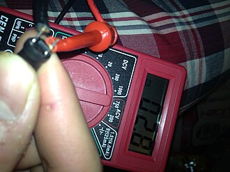
How do I tell an inductor from a resistor?
Inductors are often green or sea-foam blue; resistors are beige, blue, or pink. On a multimeter: inductor ≈ 0Ω (short), resistor shows its rated value. Some inductors have a visible wire winding on the body. An LCR meter gives the definitive measurement.
Why is the unit microhenries (µH) and not henries?
One henry is enormous — a 1H inductor would be a large, heavy coil. Most real inductors range from a few nanohenries (RF circuits) to a few millihenries (audio/power). Microhenries (µH) sits in the middle of the most common range and keeps the numbers manageable.
What is the tolerance band telling me?
Tolerance is the allowed variation from the labeled value. A 100 µH ±10% (silver) inductor can be anywhere from 90–110 µH. For RF and filter circuits, use ±5% (gold) or better. For power supply chokes, ±20% (black) is usually fine.
What does a Military Spec (wide silver band) inductor mean?
A wide silver Band 1 identifies a MIL-SPEC component built to military quality standards — tighter tolerances, extended temperature range, and stricter reliability testing. Uses a 5-band code with different reading rules. Found in military, aerospace, and high-reliability industrial equipment.
What inductance do I need for a buck converter?
Typical buck converter inductors range from 1–100 µH depending on switching frequency — higher frequency allows smaller inductance. At 500 kHz, 4.7–22 µH is common. At 100 kHz, 22–100 µH is typical. Use our Planar Inductor Calculator to design a PCB inductor for custom values.
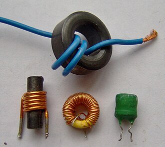
Inductor Types & When Color Codes Apply
Color band coding applies only to axial through-hole inductors — the cylindrical components with wire leads coming out of each end. Other inductor package types use different marking systems:
| Type | Marking | Typical Range | Application |
|---|---|---|---|
| Axial (color bands) | EIA-RS-279 color code | 1 µH – 100 mH | Through-hole circuits, vintage electronics, RF chokes |
| SMD chip (numeric code) | 3-digit / R-notation | 1 nH – 10 mH | PCB surface mount, switching supplies, RF |
| Toroid (no marking) | Core color indicates material | 1 µH – 100 mH | Power supplies, EMI filters, custom RF coils |
| Shielded power (numeric) | Value printed directly | 1 µH – 2.2 mH | Buck/boost converters, DC-DC modules |
| PCB spiral (no marking) | Calculated from geometry | 1 nH – 100 µH | RF, NFC/RFID, wireless charging |
Related Tools on CircuitsLab Wiki
- Resistor Color Code Calculator — Same digit-color system, but result in ohms instead of µH
- Planar Inductor Calculator — Design a PCB spiral inductor with a specific inductance, Q-factor and SRF
- RC / LC Filter Calculator — Use your decoded inductance to calculate LC filter cutoff frequency
- PCB Via Current Calculator — Size the vias connecting your inductor pads for high-current designs
- PCB Trace Width Calculator — Ensure traces feeding your inductor can carry the operating current
- 555 Timer Calculator — Design oscillator circuits to test inductors at a known frequency