Boolean Algebra Solver & Truth Table Generator
Truth Table Generator
Karnaugh Map (K-Map) Visualizer
Step-by-Step Simplification
Canonical Forms & Lists
Enter any Boolean expression using AND, OR, NOT, XOR, NAND, or NOR — and instantly generate its complete truth table with sub-expression steps, Sum of Products (SOP), Product of Sums (POS), minterm/maxterm lists, and a Karnaugh map. Free, no sign-up, works in your browser.
AB or A*B → ANDA+B → OR!A or A' → NOTA^B → XORNAND(A,B) → NANDNOR(A,B) → NOR(A+B)*C → ParenthesesA XNOR B → XNOROperator precedence (high to low): NOT → AND → XOR → OR. Use parentheses to override. Variables must be single capital letters A–H.

What Is Boolean Algebra?
Boolean algebra is the branch of mathematics that deals with variables that can only take two values: True (1) and False (0). Defined by George Boole in 1854 and extended by Claude Shannon in 1937 to describe electrical circuits, it is the mathematical foundation of every digital system ever built — from the simplest logic gate to a modern CPU with billions of transistors.
In Boolean algebra, variables represent logical conditions (a switch is ON or OFF, a sensor reading is HIGH or LOW) and operators combine them into expressions that describe how a circuit or program behaves. This solver parses your expression and generates a truth table showing every possible input combination and the resulting output — instantly and without manual calculation.
Logic Gates & Boolean Operators
Every Boolean operator corresponds to a physical logic gate in digital electronics. Understanding both the algebraic expression and the gate symbol is essential for digital design coursework.
AND Gate — Conjunction
Output is 1 only when ALL inputs are 1. Equivalent to
a series circuit — all switches must be closed for current to flow.
Notation: A * B, AB, or A · B.
| A | B | A AND B |
|---|---|---|
| 0 | 0 | 0 |
| 0 | 1 | 0 |
| 1 | 0 | 0 |
| 1 | 1 | 1 |
OR Gate — Disjunction
Output is 1 when ANY input is 1. Equivalent to a
parallel circuit — any closed switch allows current to flow.
Notation: A + B.
| A | B | A OR B |
|---|---|---|
| 0 | 0 | 0 |
| 0 | 1 | 1 |
| 1 | 0 | 1 |
| 1 | 1 | 1 |
NOT Gate — Inverter
Output is the complement of the input.
Turns 1 into 0 and 0 into 1. Every other gate can be built from
AND + NOT or OR + NOT combinations.
Notation: !A or A'.
| A | NOT A |
|---|---|
| 0 | 1 |
| 1 | 0 |
XOR Gate — Exclusive OR
Output is 1 when inputs are different.
Used in binary adders, error-detection circuits, and encryption.
XOR of a value with itself always returns 0;
XOR with 1 always flips the bit.
Notation: A ^ B.
| A | B | A XOR B |
|---|---|---|
| 0 | 0 | 0 |
| 0 | 1 | 1 |
| 1 | 0 | 1 |
| 1 | 1 | 0 |
NAND Gate — Universal Gate
NOT AND — output is 0 only when ALL inputs are 1.
NAND is a universal gate: any Boolean function
can be implemented using only NAND gates. Modern CMOS circuits
use NAND gates as the primary building block.
Notation: NAND(A,B) = !(A*B).
| A | B | NAND |
|---|---|---|
| 0 | 0 | 1 |
| 0 | 1 | 1 |
| 1 | 0 | 1 |
| 1 | 1 | 0 |
NOR Gate — Universal Gate
NOT OR — output is 1 only when ALL inputs are 0.
NOR is also a universal gate. The original TTL logic families
(7400-series) used NAND; ECL logic families used NOR as the
fundamental cell.
Notation: NOR(A,B) = !(A+B).
| A | B | NOR |
|---|---|---|
| 0 | 0 | 1 |
| 0 | 1 | 0 |
| 1 | 0 | 0 |
| 1 | 1 | 0 |
Boolean Algebra Laws & Identities
These laws are used to simplify Boolean expressions into their minimal form — reducing the number of gates needed to implement a circuit. Every step-by-step simplification in this solver names the law applied.
| Law | AND form | OR form |
|---|---|---|
| Identity | A · 1 = A | A + 0 = A |
| Null / Annihilator | A · 0 = 0 | A + 1 = 1 |
| Idempotent | A · A = A | A + A = A |
| Complement | A · A' = 0 | A + A' = 1 |
| Double Negation | !!A = A | |
| Commutative | AB = BA | A+B = B+A |
| Associative | (AB)C = A(BC) | (A+B)+C = A+(B+C) |
| Distributive | A(B+C) = AB+AC | A+(BC) = (A+B)(A+C) |
| Absorption | A(A+B) = A | A+AB = A |
| De Morgan's 1st | !(A+B) = !A · !B | |
| De Morgan's 2nd | !(A·B) = !A + !B | |
| Consensus | AB + A'C + BC = AB + A'C | |
Understanding SOP, POS, Minterms & Maxterms
Sum of Products (SOP)
SOP is a canonical form that expresses a Boolean function as an OR of AND terms. For each row where output = 1, write an AND term using all variables (complemented if the variable is 0 in that row). Example: if output is 1 at rows (A=0,B=1) and (A=1,B=1):
F = A'B + AB = B(A' + A) = B
SOP maps directly to a two-level NAND-NAND circuit — the most common implementation in standard cell ASIC design.
Product of Sums (POS)
POS expresses the function as an AND of OR terms. For each row where output = 0, write an OR term using all variables (complemented if the variable is 1 in that row). Example: if output is 0 at row (A=0,B=0):
F = (A + B)
POS maps to a two-level NOR-NOR circuit. SOP and POS always represent the same function — they are dual forms of each other, related by De Morgan's laws.
Minterms (Σm notation)
A minterm is a row where the output equals 1. Each row is numbered by treating the input combination as a binary number. Row A=1, B=0, C=1 is row 5 (101 in binary) = minterm m5. The function written in minterm notation:
F(A,B,C) = Σm(1,3,5,7) — output is 1 at rows 1,3,5,7
Maxterms (ΠM notation)
A maxterm is a row where the output equals 0. Maxterms are the dual of minterms — the same row numbers that are not in the minterm list. The same function in maxterm notation:
F(A,B,C) = ΠM(0,2,4,6) — output is 0 at rows 0,2,4,6
Both representations contain identical information — choose whichever has fewer terms for a more compact expression.
What Is a Karnaugh Map (K-Map)?

A Karnaugh Map (K-Map) is a visual method for minimizing Boolean expressions, invented by Maurice Karnaugh in 1953. Instead of applying algebraic laws step by step, you fill in the truth table values on a grid arranged in Gray code order (adjacent cells differ by exactly one variable) and then circle groups of 1s.
The key rules for grouping:
- Groups must contain 1, 2, 4, 8, or 16 cells (powers of 2)
- Groups can wrap around the edges of the map (the map is toroidal)
- Each group must be as large as possible
- Every 1 must be covered by at least one group
- Fewer, larger groups → simpler final expression
- Don't-care conditions (X) can be included in groups if they help make groups larger
A group of 2 cells eliminates 1 variable. A group of 4 eliminates 2 variables. A group of 8 eliminates 3 variables. This is why K-maps produce minimal SOP expressions faster than algebraic simplification for 4-variable functions.
Practical Applications of Boolean Algebra
Digital Circuit Design
Every combinational logic circuit — adders, multiplexers, decoders, comparators, priority encoders — is described by Boolean expressions. Simplifying the expression with K-maps or algebraic reduction directly reduces gate count, silicon area, and power consumption in ASIC and FPGA designs. Use our Digital Logic Simulator to visualize the circuit from any expression this solver generates.
FPGA / VHDL / Verilog Design
Hardware Description Languages (VHDL and Verilog) express logic as
Boolean equations. The SOP form output from this solver can be written
directly as: assign F = (A & !B) | (!A & B); in Verilog
or F <= (A AND NOT B) OR (NOT A AND B); in VHDL.
Synthesis tools then minimize and map these to available FPGA LUT resources.
Software Conditional Logic
De Morgan's Laws apply directly to programming conditionals.
if (!A && !B) is identical to if (!(A || B))
— the solver proves this by showing both expressions produce identical truth tables.
Boolean simplification can reduce nested if chains to simpler,
more readable conditions.
Discrete Mathematics & Computer Science
Boolean algebra is the formal foundation of propositional logic taught in
discrete mathematics courses. The operators map directly: conjunction (∧) = AND,
disjunction (∨) = OR, negation (¬) = NOT, implication (→) = !A + B,
biconditional (↔) = XNOR. This solver handles all standard Boolean operators
for both digital electronics and discrete math coursework.
Database Query Optimization
SQL WHERE clauses with multiple AND/OR/NOT conditions are Boolean expressions. Query optimizers apply Boolean algebra laws — especially absorption and De Morgan's transformations — to rewrite queries into forms that better match available indexes. Understanding Boolean simplification helps write more efficient queries.
Boolean Search (Google, Legal, Academic)
Advanced search queries use Boolean operators: cat AND dog NOT fish,
(python OR javascript) AND tutorial. Understanding precedence
(AND before OR, unless parenthesised) is essential for precise results —
the same operator precedence rules this solver uses.
Video: Logic Gates, Truth Tables & Boolean Algebra — Complete Tutorial
This comprehensive 54-minute tutorial by The Organic Chemistry Tutor covers everything from binary numbers through AND, OR, NOT, NAND, NOR gates, truth table construction, writing SOP and POS expressions, minterms, maxterms, and Boolean algebra simplification rules. With over 1.3 million views, it is one of the highest-rated introductory digital logic tutorials available — ideal for students taking their first digital electronics or discrete mathematics course.
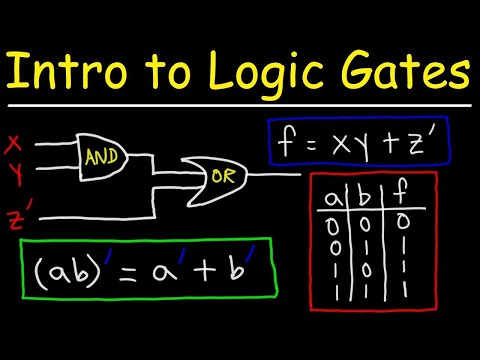
📺 Logic Gates, Truth Tables, Boolean Algebra — AND, OR, NOT, NAND & NOR — The Organic Chemistry Tutor. Covers all six logic gates, truth table construction, SOP/POS forms, minterms, maxterms, and Boolean simplification rules in one complete video.
Frequently Asked Questions — Boolean Algebra & Truth Tables
Common questions about Boolean algebra, logic gates, truth tables, K-maps, and how to use this solver — answered for students and engineers.
Using the Solver
How do I enter a Boolean expression?
Use capital letters for variables (A, B, C…).
AND: AB or A*B.
OR: A+B.
NOT: !A or A'.
XOR: A^B.
NAND: NAND(A,B).
NOR: NOR(A,B).
Use parentheses for grouping: (A+B)*!C.
Operator precedence is NOT → AND → XOR → OR.
How many variables can I use?
The solver supports up to 8 variables (A–H), generating a truth table with up to 256 rows. For 4 variables (16 rows), the K-map generator produces a standard 4×4 map. For 2–3 variables, it produces 2×2 and 4×2 maps respectively.
How do I prove two Boolean expressions are equivalent?
Enter both expressions separately and compare their truth tables.
If every row produces the same output in both tables, the expressions
are logically equivalent. For example, enter !(A+B)
and !A*!B — the identical truth tables prove
De Morgan's First Law.
What does the sub-expression column feature show?
For complex expressions like (A+B)*(!C), the solver
adds intermediate columns showing the result of each sub-expression:
first a column for (A+B), then one for (!C),
then the final result. This makes it easy to trace how the final
output is reached at each row — essential for understanding and
debugging logic.
Concepts & Theory
What is SOP vs POS form?
Sum of Products (SOP) is an OR of AND terms — one AND term per row where output = 1. It maps to NAND-NAND circuits. Product of Sums (POS) is an AND of OR terms — one OR term per row where output = 0. It maps to NOR-NOR circuits. Both forms represent the same function and are used depending on which has fewer terms or which gate type is available.
What is a Karnaugh Map and why use it?
A K-Map is a 2D grid of truth table values where adjacent cells differ by exactly one variable. You circle groups of 1s (in powers of 2) to identify terms that can be merged, eliminating variables. A group of 4 eliminates 2 variables from the SOP term. K-maps produce minimal expressions faster than algebraic simplification for functions with 3–4 variables.
What are don't-care conditions in a truth table?
Don't-care conditions (marked X) are input combinations that either never occur or where the output doesn't matter to the design. In K-map simplification, don't-cares can be treated as either 0 or 1 — whichever allows larger groupings and therefore simpler expressions. Common in BCD decoders where inputs 1010–1111 (10–15) are invalid.
Why are NAND and NOR called universal gates?
Because any Boolean function can be built using only NAND gates — or only NOR gates. AND, OR, and NOT are each constructable from 2–3 NAND gates. This is why CMOS standard cells in modern chips are almost entirely NAND and NOR based — a single gate type simplifies fabrication, layout, and timing analysis. Use our Digital Logic Simulator to verify any NAND-only equivalence circuit interactively.
What is the difference between XOR and XNOR?
XOR outputs 1 when inputs are different:
A^B = A'B + AB'.
XNOR outputs 1 when inputs are the same:
A XNOR B = AB + A'B' — it is the complement of XOR.
XNOR is used in equality comparators, error detection circuits,
and CRC generators. XOR is used in binary adders and cryptographic
operations.
What is the Consensus Theorem?
The Consensus Theorem states: AB + A'C + BC = AB + A'C.
The term BC is redundant and can be eliminated because it is
"covered" by the other two terms. This is a less obvious simplification
that algebraic manipulation and K-maps can both identify, but which
students often miss when simplifying by hand.
Advanced Boolean Concepts
Duality Principle
Every Boolean theorem has a dual: swap AND↔OR and 0↔1 throughout
and the resulting expression is also true.
Example: Identity law A + 0 = A has dual A · 1 = A.
De Morgan's laws are duals of each other.
This means every circuit can be built in two equivalent forms —
one using AND/OR and one using the complementary operators.
Functional Completeness
A set of gates is functionally complete if it can implement any Boolean function. Minimum complete sets include: {NAND}, {NOR}, {AND, NOT}, {OR, NOT}. The set {AND, OR} alone is NOT complete (cannot implement NOT). {XOR, AND} is also not complete. This is why every digital IC library includes NAND and NOR as its primary cells — they provide functional completeness with optimal CMOS transistor efficiency (4 transistors per 2-input gate).
Shannon's Expansion Theorem
Any Boolean function can be expanded around a variable:
F(A,B,C) = A · F(1,B,C) + A' · F(0,B,C).
This is the theoretical basis of how FPGA lookup tables (LUTs) work —
a 4-input LUT stores all 16 values of a 4-variable truth table in
a small SRAM, implementing any 4-variable Boolean function without
re-routing. Shannon's expansion also underlies binary decision diagrams (BDDs)
used in formal verification.
Quine-McCluskey Method
The Quine-McCluskey algorithm is a tabular method for Boolean minimization that works for any number of variables — unlike K-maps which become impractical above 5–6 variables. It systematically finds all prime implicants (the largest possible groupings) and selects a minimal cover. This is the algorithm used by logic synthesis tools in EDA software like Yosys, Synopsys Design Compiler, and Cadence Genus — the same tools used to synthesize Verilog and VHDL for ASIC and FPGA production chips.
Related Free Tools on CircuitsLab Wiki
- Digital Logic Simulator — Build and simulate circuits from Boolean expressions with real-time gate visualization
- Logic Gates Truth Table Visualizer — Interactive truth tables for each individual gate type
- 7-Segment Display Decoder — BCD to 7-segment Boolean decoder with truth table
- Planar Inductor Calculator — PCB spiral coil inductance and Q-factor
- PCB Trace Width Calculator — IPC-2221 trace current capacity
- PCB Via Current Calculator — Via sizing, aspect ratio, and thermal audit